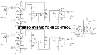
Stereo Hybrid Tone Control
Stereo Hybrid Tone Control is made by Barlex Respectaizer, a fairly simple tone control circuit using several NPN transistors and also a dual opamp IC for the final amplifier, you can make this Hybrid Tone Control circuit yourself because the schematic and PCB can be downloaded for free at the end of the posting. Here's the circuit diagram of its tone control:
The stereo Hybrid tone control scheme, using a combination of 2N5551 and 2N222 transistors. For initial gain and then go into bass and treble settings, bass treble settings use a stereo potentiometer. then the signal is amplified and amplified by the U1 IC Dual Op-Amp buffer circuit, you can use equivalent dual op-amp ICs for example JRC4558, TL082. TL072, NE5532, AD823. OPA2134 etc. This tone control is low distortion, clarity sound, good separation, good bass attack.
The circuit Tested (See Youtube Video) with symmetrical supply, the maximum voltage rating is the 12v-0-12v transformer. Use a minimum 500mA Stepdown transformer.
Part List:
1 2N2222 Q2,Q4
2 2N5551 Q1,Q3
3 1000uF 25V C17,C18
4 3P MINI TERMINAL T2,T1 XHB-TH_3PIN
5 1K 1W R33
6 220uF C21 CAP-D8.
7 1N4002 D1,D2,D3,D4
8 3.3uF C2,C3,C4,C5,C6,C7,C8,C1
9 NE5532 U1
10 3P TERMINAL T3
11 B50K P1,P3,P2
12 2.2K R1,R2,R3,R4,R23,R24,R29,R30,R34
13 100K R5,R11,R25,R26,R7,R9
14 330K R6,R10,R12,R8
15 4.7K R13,R14,R15,R16,R17,R19
16 1K R18,R20,R27,R28
17 10K R21,R22
18 220R R31,R32
19 LED-3MM LED LED-3MM 1
20 22nF C14,C16,C9,C11
21 4.7nF C13,C15
22 100nF C19,C20,C10,C12
For ease of assembly, you can create your own or download the PCB layout is Gerber files. The following image layout PCB design 2 layer:
See Also
Parametric Tone Control 4558
LM1036 Tone Control Circuit
Download:
Schematic + Gerber Files Stereo Hybrid Tone Control
The stereo Hybrid tone control scheme, using a combination of 2N5551 and 2N222 transistors. For initial gain and then go into bass and treble settings, bass treble settings use a stereo potentiometer. then the signal is amplified and amplified by the U1 IC Dual Op-Amp buffer circuit, you can use equivalent dual op-amp ICs for example JRC4558, TL082. TL072, NE5532, AD823. OPA2134 etc. This tone control is low distortion, clarity sound, good separation, good bass attack.
The circuit Tested (See Youtube Video) with symmetrical supply, the maximum voltage rating is the 12v-0-12v transformer. Use a minimum 500mA Stepdown transformer.
Part List:
1 2N2222 Q2,Q4
2 2N5551 Q1,Q3
3 1000uF 25V C17,C18
4 3P MINI TERMINAL T2,T1 XHB-TH_3PIN
5 1K 1W R33
6 220uF C21 CAP-D8.
7 1N4002 D1,D2,D3,D4
8 3.3uF C2,C3,C4,C5,C6,C7,C8,C1
9 NE5532 U1
10 3P TERMINAL T3
11 B50K P1,P3,P2
12 2.2K R1,R2,R3,R4,R23,R24,R29,R30,R34
13 100K R5,R11,R25,R26,R7,R9
14 330K R6,R10,R12,R8
15 4.7K R13,R14,R15,R16,R17,R19
16 1K R18,R20,R27,R28
17 10K R21,R22
18 220R R31,R32
19 LED-3MM LED LED-3MM 1
20 22nF C14,C16,C9,C11
21 4.7nF C13,C15
22 100nF C19,C20,C10,C12
For ease of assembly, you can create your own or download the PCB layout is Gerber files. The following image layout PCB design 2 layer:
Video Assembly and Test
See Also
Parametric Tone Control 4558
LM1036 Tone Control Circuit
Download:
Schematic + Gerber Files Stereo Hybrid Tone Control


How is the sound quality
ReplyDelete