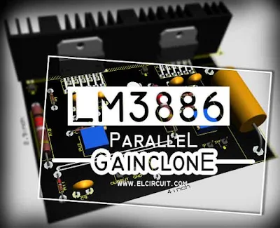
Parallel Gainclone Power Amplifier LM3886
For you audio enthusiasts, it is not unfamiliar with this LM3886 IC. This IC is very popular by various DIY audio circles because this amplifier has a small distortion, very small. Also called Gainclone Amplifier, which is very similar to the performance with Amplifier Tubes. And it is also suitable for controlling speaker subwoofer let alone combined with Power Amplifier Circuit using IC LM1875, is perfect for your home theater audio usage. See also: Stereo Gainclone Power Amplifier LM1875
The basic circuit power amplifier uses one IC LM3886
IC LM3886 which can power up to 135W Instantaneous Peak Output Power Capability. And 68W Continuously, if supplied with 35V DC voltage.
For the purpose of subwoofer then also require power which is also not small. So here I will share the LM3886 parallel circuit to increase the power of this Power Gainclone. Here's the circuit scheme and also the PCB Layout:
Component Lists:R1=47K
R2=10K
R3=200K
R4=
R5=0,22R 3W
R6=
R7=10K
R8=200K
R9=5K1
R10=0,22R 3W
R11=2K2 1W
C1=4u7
C2=200pF
C3=47pF
C4=
C5=
C6=200pF
C7=47pF
C8=100uF/50V
C9=100N
U1=LM3886/ LM3886TF
U2=LM3886/ LM3886TF
You can use more LM3886 by multiplying the circuit diagram.
See also
See also LM3886 Stereo:


can I have gerber file for this amplifier?
ReplyDeletePlease wait sir. i will upload on my youtube.
DeleteYou have "R11" in series with the speaker line, in the circuit diagram, that's not right.
ReplyDelete