2800W High Power Amplifier Circuit [Updated!]
Mono high power amplifier circuit is actually powerful, output about 1400 W, but if this high power amplifier circuit is doubled and you want to create stereo power amplifier, this high power amplifier circuit the necessary components and PCB requires two-fold. So if the stereo high power amplifier 2 X 1400W Power Output ( 2800W ).
Power Amplifier Circuit Diagram is still less by looking at the circuit that was so below, the finished circuit has been added with gains, using two JRC4558 IC the picture IC where it can be seen below. For circuit buffers, drivers, and booster use multiple transistors and other components (can be seen listed component). And high power amplifier project that is so below is just part of the buffer and driver while the booster has not been made. For additional transistors in the booster or high power amplifier, end scheme can be found Booster output power amplifier. For bass booster using this circuit:
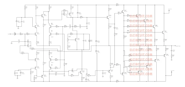
High Power Amplifier PA schematic diagram:
2800W high power audio amplifier circuit diagram
Part List :Power Amplifier Circuit Diagram is still less by looking at the circuit that was so below, the finished circuit has been added with gains, using two JRC4558 IC the picture IC where it can be seen below. For circuit buffers, drivers, and booster use multiple transistors and other components (can be seen listed component). And high power amplifier project that is so below is just part of the buffer and driver while the booster has not been made. For additional transistors in the booster or high power amplifier, end scheme can be found Booster output power amplifier. For bass booster using this circuit:
New High Power Amplifier Circuit:
High Power Amplifier PA schematic diagram:
2800W high power audio amplifier circuit diagram
Resistor
R1_____560ΩR2_____100Ω
R3_____2K2Ω
R4_____560Ω
R5_____1Ω
R6_____27KΩ
R7_____10KΩ
R8_____100Ω
R9_____100Ω
R10____100Ω
R11____12KΩ
R12____100Ω
R13____100Ω
R14____100Ω
R15____27KΩ
R16____2K2Ω
R17____560Ω
R18____100Ω
R19____10KΩ
R20____330Ω
R21____47Ω 2W
R22____56Ω
R23____2K2Ω
R24____22Ω
R25____56Ω
R26____180Ω
R27____500-1KΩ Trim
R28____560Ω
R29____56Ω
R30____56Ω
R31____22Ω 1W
R32____5Ω6 2W
R33____10Ω
R34____180Ω
R35____100Ω
R36____22Ω 2W
R37____180Ω
R38____56Ω
R39____47Ω 2W
R40____5Ω6 2W
R41____10Ω
R42____10Ω
R43____10Ω
R45____10Ω
R46____0.22Ω 5W
R47____0.22Ω 5W
R48____0.22Ω 5W
R49____0.22Ω 5W
R50____10Ω 5W
Capacitor
C1_____1цFC2_____1.5nF
C3_____0.1цF 250-275V
C4_____0.1цF 250-275VC5_____100nF
C6_____100цF 50V
C7_____39pF
C8_____330pF
C9_____330pF
C10____330pF
C11____47nF 250-275V
C12____220nF 250-275V
Transistor
T1_____MJE340T2_____2N5551 / C2240
T3_____2N5551 / C2240
T4_____2N5551 / C2240
T5_____2N5551 / C2240
T6_____2N5401 / BF423
T7_____2N5401 / BF423
T8_____2N5401 / BF423
T9_____2N5401 / BF423
T10____MJE350
T11____B1186
T12____TIP127
T13____D1763
T14____D1763
T15____B1186
T16____C5198
T17____A1941
T18____2SC2922 / MJ15024G
T19____2SC2922 / MJ15024G
T20____2SA1216 / MJ15025G
T21____2SA1216 / MJ15025G
Buy these parts, go to Allchips.
Installation with booster

Password RAR: elcircuit.com
File is using to edit schematic and making Layout PCB by using Proteus Software
Other high power amplifier circuit:


![Layout design high power amplifier [Edited Version] Layout PCB high power amplifier [Edited Version]](https://blogger.googleusercontent.com/img/b/R29vZ2xl/AVvXsEhV_FndJYPKACAO060ANpvgEW2XPuEhcsS2fmwvdgVE1x-vSLfCZbi6q4X28lE8EVSJYpkGOeI0SiAn0gvmaaz_wYXl4l31XCDmwz49gd3M36P879zaE_PE5m-H0xYqv1n8ISsQ_Qn4Eiw/s320-rw/Layout+High+power+amplifier.jpg)
what is the power supply voltage this need, sir?
ReplyDeletehelo sir,
ReplyDeletegood day, is the power amp capable of driving 4ohm load and what is the working voltage
it would be a big help to us hobbyist if you can send us the needed specs thanks....goodluck.
jeff
whats the part numbers for the different type of diodes you used
ReplyDeleteWirajith : power supply need 60 to 90 VDC
ReplyDeletepogi : thanks sir
ano: you can use 1n4007 and dioda 1n4148 for different diode type
Please send me the pbc layout in my Gmail account [email protected]
DeleteThanks
what is value of D3 and D4 diode
ReplyDeleteD3 and d4 using 1n4007 , d1 and d2 is zener diode 24V
DeleteHello guys please send me the pbc layout in my Gmail
ReplyDelete[email protected]
Thanks
Hi Abrie door,
Deleteplease check your inbox email, or on spam folders.
Thanks
Hi there, can you reupload clear pcb design. I need this power amplifier to built it.
ReplyDeletei will update quickly.
DeleteHello guys please send me the pbc layout in my Gmail
ReplyDelete[email protected]
next i will update the pcb layout
Deletehi :) can u send the PCB layout & design please :) [email protected] thankyou sir ^^
ReplyDeleteyou can downoad it, is attach in post.
DeletePlease send me the pbc layout in my Gmail account [email protected]
ReplyDeleteThanks
you can download it, is attach in post.
DeleteHelloو
ReplyDeleteI have a question resistance is the 31 two numbers?
and Where is the resistance 44?
R44 is 10ohm 1/2 watts , please see the first schematic diagram
Deleteand How much input Ampere needed?
ReplyDeleteHello Naser,
DeleteInput ampere of voltage source is 20Ampere , use the toroid transformer for best sound quality
I'm Waitiiiiiiiing!
ReplyDeleteyou can see it
DeleteThanks a lot for the information. I was looking for this.
ReplyDeleteyoure welcome sasmita
DeleteWhat are the values of diodes used in the circuit?
ReplyDeleteyou can see at the commment before. or on the first circuit diagram (updated)
Deletesir. its very superub AMP, but what is the transformer current and voltage ratings, how many output transistors can be used. in LAPANGAN Sir Video..used 10sets of output transistors using. like that willbe assembled it?
ReplyDeleteHello Bhushan, thanks for visit elcircuit.
Deletethe transformer rating you must use minimum 10A with voltage 45v. And the final transistor can be using 6set Sanken.
This is a nice post but I think you need to edit your post. There are two different schematics here, the list of components matches the second schematics in blue coloring but your Proteus file matches the first schematic. Now the question is which schematic is the correct one? Thanks
ReplyDeletethe first schematic is correct.. but you can modify on the second schematic.
DeleteHii,
ReplyDeleteCould you mail me the pcb layout diagram for this mail: [email protected]
pcb layout is attach on the post above sir.
DeleteHello sir
ReplyDeleteCan you send me the pcb layout again in my gmail
abriedoor @gmail.com
thanks...
Hello sir
ReplyDeleteCan you send me the pcb layout again in my gmail
abriedoor @gmail.com
thanks...
Hi Abrie,
DeleteYou can download at the post 2800w circuit power amplifier.
please send me pcb lay-out [email protected] thank you
ReplyDeleteDownload the .rar file its include schematic and ppcb layout
Deletehow much this voltage bias sir?.. and this is a zero volt?..
ReplyDeleteit is zero volt,
Deleteis this proven and tested?
ReplyDeleteyes its tested
Deletehow about voltage bias sir
ReplyDeletezero volt on voltage bias .
Deletewhat is the value of capacitor c5 and resistor r44?..
ReplyDeletec5 = 100n r44 = 10 Ohm 0.5W
DeleteSeth Yirenkyi
ReplyDeletePlease can you send me the pcb layout in my gmail
[email protected]
Please can you send me the pcb layout in my gmail
ReplyDelete[email protected]
PCB Design is attach on .RAR file, is proteus format
Deletedo you have a video on this that is proven and tested?.
ReplyDeleteThis my old power amplifier i have, but i dont have the video test its proove working.
Deletepls share the layout file in pdf.
ReplyDeletePlace send me PCB layout my gmail id
ReplyDeletetolong gambar PCB layout dalam format pdf
ReplyDeletehttps://www.ecguideline.xyz/2018/12/what-is-ujt-ujt-construction.html
ReplyDelete