How to make BTL Amplifier Class-D UcD Superlite
This time I will tutorial on how to BTL amplifier class-d UcD Superlite PCB 10x10cm, why in BTL? the main goal is to increase the power to the maximum and not change the sound character of this class-D UcD Superlite
Because the character of the sound produced by this class-d Ucd Superlite, I like it the most, it can be flat, the sound produced is clear, the bass is soft and not oversized and is suitable for use. sub to middle speakers, if it is used for a high, half-bridge topology I think it is very sufficient.
Because many people request how to build this Superlite UcD amplifier, and the BTL method is not as easy as previously posted to BTL an OCL amplifier.
There are many factors to maximize the BTL of this Superlite, for the UcD Superlite, this is done by inverting the input from the front between the two kits and turning it into an unbalanced input, so that it becomes balanced, you can add a series of balanced inputs.
For the BTL wiring diagram, see the image below,
 |
| BTL Class-D UcD Superlite |
In the wiring diagram above, one of the inputs is used. Because the UcD Superlite amplifier already has an input balance preamp in the kit, so we just need to use one of the input pins, we ground the + input + ground, and vice versa the + min input is grounded.
Then between the two input kits + and - combined into one input unbalance. like what I said earlier, we can add a balance input kit, so that the input from the front becomes inbalance again. and the potentiometer can be taken from the balance input add-on kit.
Class-D UcD Superlite synchronization is very important
And on the + and - output to the speaker, it must be synchronized by adding C1 and C2 as shown above, if C1 and C2 use 220nF 250V, friends can also use 100nF 250V in the picture C3, C4, C4 and C6 or say call optional synchronization.
You can see the picture below, between the two kits already says add a synchronous capacitor and says add a preamp input balance.
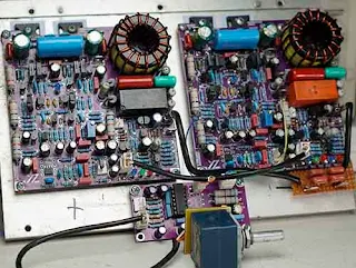 |
The two amplifier kits must have identical components, starting from the capacity value, voltage, and brand used as much as possible the same.
The amplifier PCB above is printed on JLCPCB
How to print PCB at JLCPCB can follow this step.
First, visit the JLCPCB site. then log in or register first (if you don't have an account) the button is in the top right corner click "Order Now"
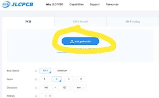
Then click "Add Gerber file"
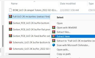
Select the Gerber file that has been downloaded at the end of the post link, but before using the downloaded file, the file with the name "Full UcD 2K mr.kartino (extract first)" must be extracted first.
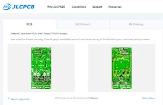
Then select Gerber one by one, then double click. Wait for the upload process to complete. then if you want to add another Gerber file, just click "Add Gerber file" again. if the three PCBs have been uploaded and you have selected the option for each PCB, click the basket, go to payment by clicking (Secure Checkout), and complete the payment on the next page. Payment can use a credit card, or debit visa, and also PayPal.
Let's continue how to make BTL Class-D UcD Superlite
because the components used to affect the PWM and amplifier gain, the amplifier gain is as much the same as possible, so if one clip is clipped the other must also be clipped.
Then the PWM is as similar as possible to the speed or frequency, between the two kits the maximum difference is not more than 20Khz. if it's close to the same or even the same freq PWM before it's synchronized it's even better.
The most important thing is synchronization, why?
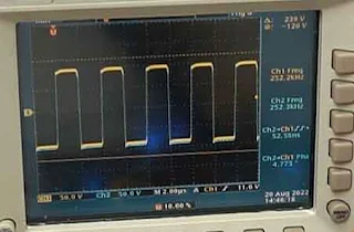 |
| Good Phase shift 4Degree |
Because in Class-D amplifiers if the PWM speed is different between kits it can cause oscillations, even the amplifier can be less than optimal, especially in the beat of the bass tone. So PWM can be measured after synchronization, it should be the same. And as much as possible the PWM phase between the two kits phase shift can be 0 degrees.
if there is a phase shift PWM difference it also affects the residual PWM output voltage, if the phase shift difference is higher, the output ripple voltage will also increase.
This Superlite UcD amplifier can be used at a power supply voltage of 65-95VDC CT and can output 2000W of power over a 4-ohm load, the efficiency is about 89%, it's good at that figure.
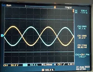 |
| Balanced Output Class-D BTL |
Then for out + - to GND, it's also as much the same as possible, otherwise the same can change the peak point of the clip. Because the gains are different, one kit has clipped the other not, surely the peak point of the BTL clip out will also go down. so use the same components to build from both kits.
Post a Comment for "How to make BTL Amplifier Class-D UcD Superlite"
Dont use outgoing links!