Hello guys, in this post I will assemble DIY a Class-D UcD1k power amplifier designed by Mr. Kartino Surodipo, which uses the LM311 IC as a comparator and IR2110 for the mosfet driver. This Class-D UcD requires only a few components and is easy to find components. Later, I will share the layout for free, which has been fixed, with an updated schema at the end of the post.
Here is the PCB layout, I designed this layout in two layers, with dimensions of 6.5cm x 20cm.
Prepare the components according to the BoM file/component list, use quality components so that the results can be maximized, or most importantly, don't bargain for the value. How to open the BoM file, upload it on the LCSC.com site, the component list will open, and it's neatly organized, if you use Ms Excel, the component list is usually messy. The BoM file is also at the end of the post.
IC LM311 and IR2110 can be SMD for alternative options, you can also use DIP ICs. so you can use only one, which can be SMD or DIP.
use a good IC because the LM311 IC also affects the PWM frequency, as well as the performance of the amplifier itself.
For the 6k8 3W Shunt Resistor I use 2x12K resistors in parallel, the installation is stacked like this. The R shunt is for 90VDC CT supply voltage, if the voltage is smaller, the resistance value can be lowered. eg 60VDC CT can use 4K7 3W.
Totem transistors other than BD139/BD140 can use 2SC2655 and 2SA1020. Actually, this can be direct without a totem. If you want without a totem, you can jump the base and emitter directly, no need to install transistors Q6, 7, 11, and 12.
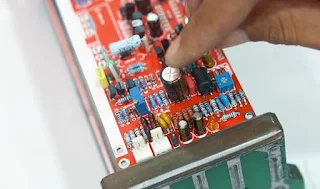
On IC LM311, because I use IC SMD, at the top of the pcb can be fitted with Elco, to pin 4 for min and 8 for + , the minimum elco voltage is 16V.
For the inductor, I used 2 double Micrometal T130-2 cores, wrapped 30 times, I got an inductance of about 30uH. The inductor can also use the MS130 3cm blue, the number of turns if the double core is 17-20x turns.
Mosfet can use irfp250, irfp260, irfp4227, or irfb4227 for the TO220 package that I have provided holes for it.
This dead time resistor is set at R17 and R18 because the original schematic is 4K2 and the one I'm using is 4K7. so I just parallel with the 47K resistor, so that the value is close to 4K2. R17 and R18, the larger the value, the narrower the dead time will be, and vice versa. What is the impact if it gets narrower? As a result, the mosfet can heat up quickly even when it's on standby, there can even be a cross which can cause the mosfet to short. if it's too loose, the effect will be that the power will be sluggish or underpowered, it can be sinus defects, or even the amplifier can fail to start.
The power released by this amplifier is around 700W RMS continuously using a 4-ohm dummy load, with a 90VDC supply, the same power as other Halfbridge class-D amplifiers, the sine signal is also smooth to near the clipping.
Assembling and tested video:
Troubleshooting
The amplifier does not run or fails to start
Try to check that all components are correctly installed according to the PCB label, also check whether the solder is completely attached or not, usually on the pad that is connected to the ground plane (solder is a bit difficult to cook because the copper is scattered, try hot soldering at 370-400 degrees Celsius), and also check soldering does not fall into another pad.
check the main supply voltage (minimum supply voltage 70VDC-95VDC CT if the part matches the PCB) and the 12V bias is correct and has also entered.
check the fuse + (U9) and - (U10), if the fuse + is blown (voltage has not entered) it can be marked the Led On is off, if the fuse is - blown (voltage has not entered) it can be marked the OCP led is on,
The OCP LED continues to light even though the bias voltage has entered it can also be marked R Sense R47 0.1 Ohm is broken.
If the OCP led is lit the amplifier will also not be able to start, because the IC IR2110 is in a shutdown state (OCP triggers the SD pin IR2110)
Check the supply voltage of LM311 (U1/U2) pin 8 to GND around +4-5VDC, and pin 4 to GND around -4 to 5VDC. This supply voltage (U1/U2) does not exist or is less than 4VDC to GND, check on R68 and R16 the value is 6K8 3W appropriate or not? if it's appropriate, check the zener D14 and D13 whether it's still good or broken or even short, this Zener D14 and D13 can use a 5V to 5.6V zener.
Check the voltage at the Anode (-) Zener D3 33V, check the voltage to gnd around 58-60VDC if using a 90VDC supply, and around 48-50VDC to gnd if the main supply voltage is 80VDC CT. if 70VDC 38-40VDC. If the voltage does not come out or it misses far from what has been mentioned, check R14 12K 1W and D3 33V and C4 220N, are the components correct.
Check the voltage can be 12V, check the voltage directly on the IC IR2110 pins pins 3 and 9 for +, pins 2 and 13 for -.
The bootsrap LED must be lit, if it dies, the led must be normal first, then check R44, check Zener D11 12V and check diode 4007 D6, check totem transistor Q11, Q12, Q6, Q7 is it correct or not?
Continue to check the audio signal and PWM, if you have an osciloscope, it will make it easier to see where the trouble is by seeing where the audio/PWM signal has reached, if you don't have one, you can use an AC voltmeter later, but if you use an AC voltmeter, it can't be accurate. just where have you been. but it's quite helpful.
Inject audio input with a sine signal with a frequency of 20-1kHz with an amplitude of 1-2Vpp, if I usually use 100Hz 1.5Vpp. Friends, if you don't have an audio generator, you can use a cellphone with an audio generator application, or if you use a PC/Laptop, you can visit this link: https://www.szynalski.com/tone-generator/, if you use a cellphone, the volume can be just polled.
check the input signal at pins 2 and 3. there must be an incoming audio signal, if you don't check again the components match or you can't see the schematic below.
then check pin 7 LM311, at this pin the signal is in the form of PWM, if you don't have an oscilloscope, you can check it using an AC voltmeter, pin 7 reads 5VAC to GND, if you want to make sure it's in the form of PWM, try turning off the input and it reads 0V. if pin 7 doesn't come out of PWM, try replacing the new IC, it's possible that the IC is worn out.
proceed directly to the HIN and LIN inputs, Oh yes, if the mosfet is already installed, don't install the bias voltage first, so that nothing happens if the PWM crosses which can cause the mosfet to break.
The HIN and LIN inputs also read PWM where HIN and LIN alternate phases, if you use an oscilloscope, the gnd probe is plugged into the mains - bias or - supply voltage. if you use the AC AVOmeter you can go to gnd and it reads 5V max, at least it depends on the amount of input.
if it is read on the LIN and HIN pins, if the IC and MOSFET are installed and the bias voltage is entered, the amplifier should be working, if it doesn't work, the problem is usually in this component:
IC IR2110, R44, D26 Diode bootstrap, R21, R22, R45, R23, D7, D12, Mosfet, then RDT is too wide R18, R17, if it is too narrow a cross occurs, which causes the mosfet to heat up and even short.
then also check the feedback component, R8 R29 C13, the component may not match its value or the soldering is not good. because these components are the core of this amplifier core
or check D8 or D9 short (but it rarely breaks when you first assemble it, but it can also happen if you install it wrong
Then check the LPF component, it is correct or not for the selection of the inductor value later, but try to range from 15-50uH first, not more or less. The choice of core is also very important, the core can use the blue MS130 or the maroon T130 Micrometal core (you can check the video). if MS130 2 double coils as much as 13-18 turns, the copper diameter is 1-1.5mm. if 2mm makes hands stick together
check capacitor C19, this capacitor can use 470nF - 2.2uf but adjusted to the speed yes and also the inductor yes. if it's safe to play 1uF, it's okay, the important thing is not the yellow audiophiler or a similar stamp, because that's not the place there :D
Hello. First of all, thanks for your effort. I had the pcb you shared made by jlc pcb and collected the card. I encountered the same problem as in the video you shared. The hissing and pwm frequency increased as the volume increased. Could you share how you solved the problem? Thanks


Bro both Gerber and schematic have same schematic link please fix this.
ReplyDeleteFixed
DeleteHello. First of all, thanks for your effort. I had the pcb you shared made by jlc pcb and collected the card. I encountered the same problem as in the video you shared. The hissing and pwm frequency increased as the volume increased. Could you share how you solved the problem? Thanks
ReplyDeletetry lowering the pwm frequency
Deletehello.I installed pcb but pwm frequency is 470khz and troid transformer is getting hot. can you help me?
ReplyDeletewhat the mosfet you use?
Delete