TDA7294 2.1 Amplifier Schematic and PCB Layout
Hello guys, in this post, Elcircuit will share the PCB layout and schematic of a power amplifier with a 2.1 Channel Amplifier system that uses an IC. The IC used is the TDA7294 IC. Because this Amplifier is a 2.1 Channel Amplifier, the IC needed to make this 2.1 amplifier is 4 ICs.
 |
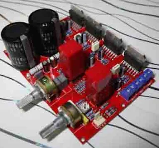
| Ready-made TDA7294 2.1 Channel Power Amplifier. |
Why use 4 ICs, not 3 because 3 channels?
Because the subwoofer amplifier uses 2 TDA7294 ICs in BTL, so that the power produced is double the power of a stereo amplifier, so the TDA7294 subwoofer amplifier will be more powerful than the stereo amplifier.
So the power for the TDA7294 stereo amplifier produces 70WATT per channel a total of 2 x 70W and the TDA7294 Subwoofer can produce up to 150WATT per subwoofer channel.
For friends who want to make this amplifier, you can use the PCB Layout for the TDA7294 2.1 Amplifier as shown below:
 |
| Download PCB Layout TDA7294 2.1 Channel Amplifier at the bottom page |
This amplifier has several features, namely: Volume control for Stereo Amplifier, separate volume control for the subwoofer amplifier, and trimpot to change subwoofer frequency or Subwoofer Low Pass Filter.
What's the sound like? Please check the video here: DIY 2.1 Amplifier With TDA7294 IC
In the pre-amplifier section in the video, try using OPA V5 from Burson Audio because it has a good sound.
This amplifier is very easy to manufacture because of its simple design and uses components that are widely available in the market, and are also inexpensive.
This amplifier requires a 24-0-24/5-10A symmetrical transformer.
For those who want to download the complete file, you can download it here:

No speaker protection
ReplyDelete