Mini Amplifier with High Power Output
Hello dear friends, I share a post about mini power amplifier circuit, Yea this is mini and simple power amplifier using the transistor and a final transistor using 2SC5200 and 2SA1943. but you make no mistake, despite the simple power amplifier designed for output power should not be underestimated. Mini power amplifiers are capable of powering up to 300W high power output amplifier if properly coupled using good components and a qualified power supply.
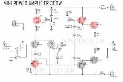
Below the circuit diagram of Mini Power Amplifier 300W:
Component list:
R1 = 56K
R2, R5 = 100R
R3 = 20K
R4 = 1K
R6, R10 = 22K
R7 = 2K7
R8 = 100K
R9 = 2K2
R11, R12 = 0,1R / 3W
C1 = 1uF nonPolarC2 = 100pF
C3 = 120pF
C4 = 220uF/50V
C5 = 47uF/100V
Q1, Q2 = BC556
Q3,Q4 = BC546
Q5 = BD139
Q6 = BD140
Q7 = 2SC5200
Q8 = 2SA1943
FU1,FU2 = 2.5Ampere
D1, D2 = 1N4148
D3, D4, D5 = 1N4007
J1 = Audio Input
J2 = Speaker Output
J3 = +42VDC
J4 = -42VDC
J5 = GND
PCB Layout Design Mini Power Amplifier
PCB Size 6cm x 7cm


thanks for great job , now do those transistors 2sa and 2sc need heat sink or not required
ReplyDeleteyes is required a heatsink for final transistor 2sc5200 and 2sa1943
DeleteQ4 is wrong type.
ReplyDeleteQ1, Q2 and Q3 are incorrectly polarized.
There are many errors in this schematic.
This amplifier wont work.
this power amplifier is tedted, what the wrong? please give me a reason
DeleteNenad is right Wahyu, Q4 is reversed bias not sure it will conduct. Q1 and Q2 should be reversed, meaning emitters should be pulling from positive rails.
DeleteOh im sorry its updated your rights
Deleteso that circuit diagram already aupgrase or not yet
Deleteupdate*
DeleteSir I love this post. Is the circuit really 300w?
ReplyDeleteHow many ampere for power supply?
ReplyDeleteCan I change the bd139 bd140 transistor???
ReplyDelete2sc5200 15 amp 250 volts . In your circuit 10 amp at 80v equals 80w not 300
ReplyDeleteThis comment has been removed by the author.
ReplyDeleteSir is the circuit been updated? I am a newbie.. assembling this one..!
ReplyDeleteHope you reply soon.
Wrong schematic. it's not working
ReplyDeleteWrong schematic. it's not working
ReplyDeleteno, its work
Deletehi is this circuit verified
ReplyDeleteyes check lastest
DeleteO par diferencial está errado, ocorreram equívocos neste amplificador. se funcionar, no máximo 80w
ReplyDeleteyes
DeleteThis amp works great. Thanks author.
ReplyDeleteThis amp works great. Thanks author.
ReplyDeleteCould you be more specific with the capacitors C1 and C2
ReplyDeleteCould you explain the working
ReplyDelete