140W Power Amplifier Circuit TIP3055 TIP2955
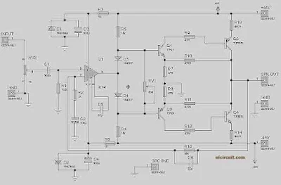
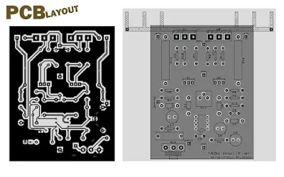
Here I am going to share the Power Amplifier circuit which uses the TIP3055 and TIP2955 transistor as the final power amplifier with power output up to 140W RMS. This power circuit is designed mini and very simple, the buffer part using single IC op-amp used is IC ua741 or LM741, then in the driver circuit using transistor TIP41 and TIP42 or TIP31 and TIP32. And the final transistor I've mentioned using TIP3055 and TIP2955 transistors, or you can upgrade by adding some transistors or also replace with higher output power, for example using 2SC5200 and 2SA1943. This circuit can be supplied with the symmetrical 45V voltage, following power circuit scheme and also PCB Layout:
Schematic Diagram:
Part List:
R1=100K R2=1k R3=1K R4=15K R5=15K R6=1K R7=47R R8=47R R9=47R R10=470R R11=470R R12=47R R13=0,22 - 0,5R/5W R14=0,22 - 0,5R/5W R15=56K
C1=220N C2=100u/25V C3=220u/25V C4=220u/25V C5=33p C6=22p
RV1=TRIMMER 500R RV2=POTENTIOMETER 50K
U1=LM741 / UA741
Q1=TIP41 Q2=TIP42 Q3=TIP2955/2N2955 Q4=TIP3055/2N3055
Troubleshooting:
- If the power amplifier is not working you must check the input voltage.
- Output speaker has DC voltage and Humming, please adjust the trimmer RV1 until the DC Voltage is it doesn't come out.
PCB Layout:


nice post
ReplyDeletethanks
DeleteSir 5200 and 1943 use sir
ReplyDeletethat will be greater more powerfull amplifier
DeleteSir 300w? Amplifier BCP design send me
ReplyDeleteSir 300w? Amplifier BCP design send me
ReplyDeleteplease search on thissite you can find it
Deletehow i can buy it from u pleas send me mail on [email protected] or whatapp on 7814202400
ReplyDeleteGood. Thank you. so much.
ReplyDeleteTeria como me mandar em pdf o arquivo para transferencia termica?
ReplyDeleteVery smart and useful....thanks very much.
ReplyDeletei do it and not works perfectly i will investigate to make a better design
ReplyDelete