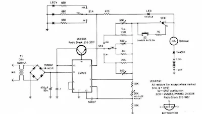
The First ac voltage from tranformator will be rectified and filtered to the LM723 voltage regulator and the NPN pass transistors setup for constant current supply. The 470 Ohm resistor is limit trickle current the momentary pushbutton (S2) is depressed, the SCR turn on , and the current flows through previously determined resistor network.SCR will be turn off if thermal cutout inside the battery pack opens up.
Thursday, March 10, 2011
Rapid battery charger schematic

Related Circuit
Subscribe to:
Post Comments (Atom)
Circuit Category
555 Circuit
Accu charger
Arduino
Audio
Audio effect
Auto Sound System
Booster Amplifier
Car amplifier
Car Stereo - Articles
CDI
Charger
Charger Circuit
Class-D Amplifier
Component's
Crossover
Detector
Digital
Fish Caller electronics
Fluorescent lamp
Gainclone Amplifier
Headphone
High power amplifier
Home Theater
Horn
ICs audio amplifier
Indicator
Input output signal
Installation
Intregated Circuit Amplifier
Inverter
Inverter Circuit
LED
Lights
Low
Low Power Amplifier Circuit
Low voltage amplifier
Microcontrol
Microcontroller
Microphone
Mobile
Mosfet Amplifier
motor
Nicad Battery charger
OCL power amplifier
Operational Amplifier Circuit
Oscilator
Other Circuit
PCB Layout
Phone
Phone battery Charger
Power Amplifier
Power Supply
Power Supply Circuit
Pre-Amplifier
Product Reviews
Protection circuit
Protector
Radio
Radio signal
Relay
RF Amplifier
Robot
Saver circuit
Sensor
Serious
Signal
Simple Circuit
Siren
Software
Solar charger
Sound
Sound System Articles
Speaker
Subwoofer - Article
Subwoofer Amplifier
Surround audio amplifier
Switch
System
Systems
Technology
Television
Tester
Timer
Tone control
Tools
Transceiver circuit
Transistor Amplifier
Transmitter
Tutorials
USB
Wireless
Love this site, what is the next list that you guys are working on. This Travel Battery Charger is amazing.
ReplyDelete