DiY 1500W 12/24V to 220V Simple Pure Sinewave Inverter Low Freq EGS 002
In this post, we will make a 12/24V to 220V pure sinewave mini inverter using the EGS 002 SPWM kit, The following is the EGS002 inverter scheme (for a clearer image, you can download the PDF version at the end of the post)
I used the EGS002 / EGS003 (EG8010) module for the SPWM, I added a totem output so that it can be used for heavy MOSFETs. For the mosfet, use 4 N channel MOSFETs, you can use IRFP4568, IRFP4468, or other N channels.
Then the PWM output goes to the primary of the step-up transformer, because this is low freq or LF mode, the transformer uses an iron transformer and only one stage.
Then the output is scanned using the FR107 diode to enter the feedback and can be adjusted at the R36 trimpot. to adjust the output voltage. and for Over Current Protection just turn it off.
This inverter supply can use a 12 to 24V battery, if you want to use a voltage above 24V the 7812 regulators can be replaced with a buck step down.
And here's the pcb layout 8x10cm with 2 layers. Design by Wahyu Eko Romadhon
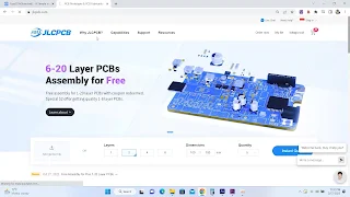
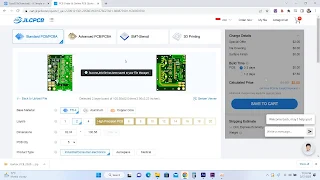
To print the pcb, you can print the pcb on JLCPCB using the Gerber file that I shared, then log in to the JLCPCB account then click order now.
Add the Gerber file, and select the Gerber file to print. wait for the file upload to finish, then you will see a pcb image looking up and down.
PCB dimensions will be filled in automatically. then select the desired pcb option. If you have clicked save to cart.
Then go to the cart, and make payment by clicking secure checkout
Then complete the payment by selecting the address and shipping method, for payment you can use a credit card, visa debit, or PayPal. then click pay, ok we just have to wait and sit pretty at home until the pcb comes. :)
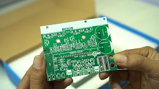
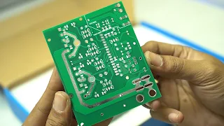
And the following pcb from JLCPCB has arrived at home. here I printed directly 50pcs.
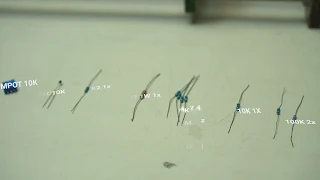
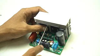
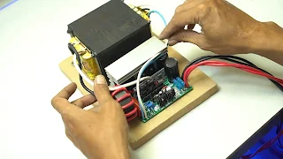
For mosfet, I use 4x mosfet irfp4568, and this small middle one is for 10k ohm ntc. Its function is as a heat sensor attached to the heatsink.
If the heatsink temperature is above forty degrees Celsius, then the fan will turn on. on the ntc leg, I have an anti-hot cable sleeve so I don't short the leg to the heatsink.
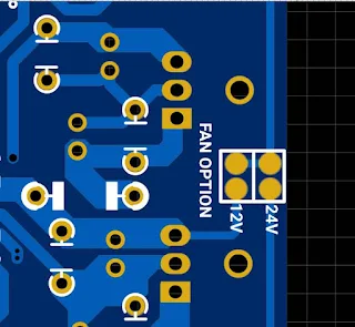
For the use of this fan, I revised it to optionally select a special fan that uses a 24V battery. if you use a 12V battery, which jumper is free.
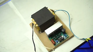
For the transformer, I use an old UPS transformer. the transformer can also use a step down transformer on the market as long as the voltage is 0, not the ct one, and the secondary voltage if the ac is input to the house's two hundred and twenty volts is still below the battery voltage
The transformer primary pairs on holes A and B are inverted freely, but one of my inductors is series, with an inductance of around 50uH - 100uH, the inductor can use the inductor used in class-d, such as 77083A7, MS157-60. Wire can use copper wire or cable like this, I use 4mm cable.
Then attach the transformer output or secondary to the pcb labeled with holes C and D, this is reversed and the installation is also free.
For the battery input, I soldered the cable directly to the PCB, actually you can use screws too because the hole is quite large with a diameter of 6mm.
Okay, let's just test it, I use a lifepo4 battery. I have arranged 8 batteries in series with a reading voltage of 26.6V.
Okay, before I turn on the switch, later I will compare the sine signal with the ac voltage at home, I use the Tektronix THS3014 oscilloscope, and all channels are isolated so each channel is free to measure anything. If oscilloscopes are generally non-isolated, don't try to measure 2 high-voltage sources directly like this. the blue line is for the house mains voltage and the yellow is for the inverter output.
First, increase it by turning the trimpot to adjust the voltage, I set it at two to two zero vol, and the sine wave looks smoother than the Home electricity.
Actually, this inverter is smooth, but the power might not be too high, I only need a small amount. because later I want to use this to turn on the instruments on my desk.
For idle current, it takes about .4-.6A of current.
so it's like that for assembling the low freq mini egs2 inverter kit, for those who want to download the pcb layout and the schematic can be downloaded them using the link below.






Link to Gerber File incorrect
ReplyDeletefixed, try again
DeletePenjelasannya cukup membantu saya untuk memahami cara kerjanya rangkaian ini .
ReplyDeleteApa bisa saya beli pcb yg sudah jadi?, kalau bisa, berapa harganya 1 keping?
Semangat berkarya, tunjukan kepada dunia kalau Indonesia bisa.
Terimakasih.
How do I change input to 48VDC and output to 120VAC
ReplyDeleteyou can use buck stepdown to 48 to 12V for egs supply, replace 7812, set ouput to 120VAC
DeletePlease what are the wire gauge you use for both the primary and the secondary coil, If I want to build 1500w?
ReplyDeleteNice job. How can I get this file to download.
ReplyDelete