In this post, I will do a tutorial on testing points before installing the mosfet on the Class D D2K Pro dual feedback power amplifier. These test points will make it easier to assemble a Class-D amplifier, I will explain directly so that you assemble this amplifier so that it can work optimally and without any engineering whatsoever on the PCB layout so that it is the same as the one I assembled. And here's how to test and see the voltage and signal waveform briefly. This is just a test point to successfully assemble class-d before installing the mosfet. If a class-d amplifier is damaged, it may be possible to do this, but if there is a damaged Class-D amplifier, it is necessary to understand the voltage and signal waveform first, so that you can find out which component is damaged. And what features are embedded in class-d it must also be understood.
I have prepared a ready-made class-d amplifier kit, but the mosfet has not been installed.
For measurement tools, prepare an oscilloscope, you can use a DSO or analog, a multimeter that has an oscilloscope, or you can also use an oscilloscope like the DSO138, to check the audio signal and the square wave is still possible even though it's not very accurate.
Prepare the PSU, for the PSU the main voltage can use a voltage of 60-90VDC CT, then install the main supply voltage, don't let it reverse install the + - and GND poles.
Install the 12V bias supply voltage, for the bias supply voltage you can use extra SMPS, or it can also be separated, but this 12V (-) voltage is not ground, because it is connected to the main supply (-) voltage.
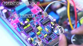
Plug the input cable, the input can use unbalance 2 & 1. then install the potentiometer, use a 10K ohm potentiometer. Set the potentiometer to the right (or connect 3 and 2 at POT10K/U15 socket), so that later the input goes directly to the Op-Amp circuit. And the limiter jumper can be removed first or the limiter is off.
For input I use an audio generator, for those who don't have it, you can use the audio output from a cellphone/PC using the audio frequency generator application, or if you don't want to download, you can use an online audio generator.
Test the power supply voltage that goes into the circuit
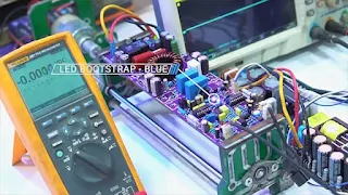
Prepare a voltmeter, then turn on the power supply, the OCP led will light up briefly, and also the protection led, if the protection led is off the relay will be active.
For active settings the relay can replace C31, the greater the value, the longer it will take and so does the death of the relay.
The blue LED BOOTSTRAP LED must light up if it doesn't light up. Usually, there is a short in the Logic IC, IC IR2110, and Transistor totem pole. or you can also check R6, and also check the 12V voltage, check the bootstrap diode, D2 D3, and resistor R31. maybe something broke.
Check first that the main supply voltage has entered or not, the avo + - plug can be tested directly after the + and - fuses, it reads 183VDC +- for (+)gnd and (-)gnd around 91.7VDC, so you can be sure the main supply voltage has entered.
Next, we check the OpAmp supply voltage, namely the R shunt resistor. R shunt is warm or hot is normal, we check the voltage after the R shunt. Plug avo min into gnd and + into R which is the + part, the voltage reads 12.1V so it's normal.
Then the min section, flip the + plug to GND and min to R shunt the min section, and it reads 12.2V this is also normal. For the normal voltage, it is about 11-12.2V, if below that or there is no voltage, the first check is the R shunt, whether the value is stretched or broken, then check the Zener diode D9 D8, check the voltage without the opamp IC, if without the opamp IC the voltage is normal, and when the IC enters the voltage drop a lot or is lost, it can be ascertained that the IC is damaged.
Check directly to the IC pin, for the dual opamp IC Inbal. voltage -12V to ground is on pin 4, +12V to ground is on pin 8, if there is no voltage on this IC pin, you can remove the ic first and then check again, if there is still no voltage, check R99 and R100 whether stretched or broken. If without the ic there is a voltage of 12V, and if the IC is given the voltage is lost, it can be ascertained that the IC is damaged,
Continue to check the voltage at the comparator IC pin TL071 for the + voltage is at pin 7 because this IC is a single opamp. And the min voltage is at foot 4. The normal voltage is in the range of 11-12V to gnd, if there is no voltage, you can try it like the Inbal IC earlier. R which is checked at R30 and R31.
If it's okay, then we check the VCC voltage on the logic IC pin, to check the VCC voltage, plug the avo - into the main supply min voltage. as I said earlier the supply voltage - the main is the same as the supply bias min.
Then plug avo + into pin 1 or 16 logic ic. And it reads 12.9VDC, and the normal voltage can be 10-15VDC, but 12-13VDC is recommended. If there is no voltage, you can check diode D2, whether it is broken or not and the path that passes through it.
If there is already a voltage, then check the VCC voltage at pin IR2110, check pins 3 and 9, the voltage is the same as the VCC Logic voltage, for pin 3, if there is no voltage you can check R1, usually it's broken and check might also be a broken line.
Test by looking at the signal wave
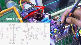
If there is a voltage, then we will test it by injecting the audio input using an audio generator, setting the frequency of the audio generator at 100Hz, and the amplitude of 1Vpp. Or set it up, it can be 20Hz-20kHz, if you use a cellphone/PC you can set the highest volume.
Then to see the signal, we use an oscilloscope, setting the oscilloscope Time /Div at 1mS, and the V/div at 5V/Div. For Time/div can be adjusted to the frequency of the audio input. For example, 1khz can be set to 500nS time/div.
The first check, make sure the input is entered, it can be checked on R44 then a sine wave will come out like audio input.
Then immediately check on Pin 1/U8/NE5532 and the output is still a sine wave, but the signal has been amplified it reads 5.8Vpp, for R gain I did increase it at 33K if 22K feels a little less gain, the Gain setting is on resistor R41, the greater the value, the gain gets bigger, and vice versa.
If the pin 1 signal does not exist or it still reads like the input signal, it can be ascertained that the IC is damaged, or it can be checked that the R gain may be incorrectly installing a smaller resistor in value.
Check pin 2 of the TL071/ U1 comparator IC, the signal is still a sine wave same as pin 1 of the Inbal IC U8.
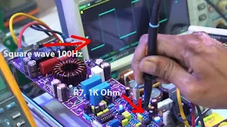
Continue to output pin 6/U1, and it reads a square wave, with the same frequency as this input at 100Hz. If the output is not squarewave, it can be ascertained that the IC is damaged, or the transistor Q1 is short.
Then check the base in Q1 or at R 7 the value is 1-kilo ohm, the signal looks the same as a square wave with pin 7 tl071.
Continue to check the collector or level shifter output, attach the probe to the anode pin D1 or diode 4148 near Q1.
The signal will read negative because the output is a reference to the voltage - bias / so it reads like the voltage - the main supply to ground.
So we can increase the vertical position until the signal is visible, if it is stuck / limit is not visible, we can increase the V/div to 10V. If you see a square wave but it's still running, sync the trigger first. This frequency still reads the same as the input at 100Hz, if you don't get a square wave like this, it can be ascertained that Q1 is damaged.
Then immediately check the logic IC input, at pin9 IC CD4049. Reads the same as the Q1 collector pin earlier.
Okay, if there is a square wave at the input pin 9, let's go straight to the mosfet driver input.
Check pins 10 and 12 of IC IR2110. Both high-in and low-in inputs must have a square wave as shown below and the frequency remains the same as the input frequency.
If we only use one probe, we don't know which is the high and low input, then we can add 1 more oscilloscope probe, it will look like the picture above the high low input IR2110, if one or both of them don't have a square wave, you can be sure the logic IC is damaged
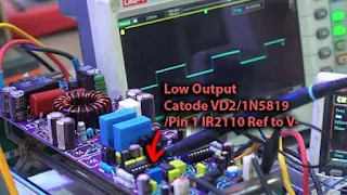
Further, check the IC IR output, check pin 1 or Output Low, This comes out the square wave, the frequency is still the same as the input 100Hz.
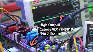
Then also check the output high at Pin 7 IC, or at the VD1 cathode. But return the vertical position of the oscilloscope to the middle first so that it can be read. because earlier we raised it to read the referenced Low Side with a 12V bias voltage. then out a square wave like this picture above. The square wave drew actually appears and disappears appears and disappears according to the input frequency.
If it doesn't come out like it, you can be sure the IC is damaged, or check the Transistor Totem, Q 8 9 10 11, maybe something is short.
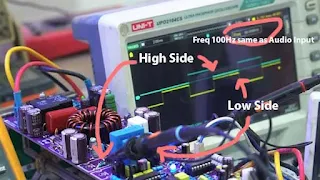
Next check directly to the Gate Mosfet then it comes out the same as the output of the IR 2110 pin, for the High and Low Side it is the same as the IR2110 output. A square wave appears with the same freq as the input, and off and on time will alternate between its low and high side.
For the low side, set the Vertical position of the oscilloscope to the top as before. If you don't get a square wave like this, it can be ascertained that the totem pole transistor is damaged, maybe there is a short Q8-9-10-11. Also, check R Gate and diode maybe both are broken. Suggestion says use R Gate at 1/2Watt. If a square wave comes out of the gate mosfet like the picture above, we can directly attach the mosfet.
I am using 4xIRFP260N mosfet, mosfet can use IRFP250N, IRFP4227, IRFP4242, IRFP4229, or N-Channel Mosfet specifically for Class-D Amplifier.
I have installed the mosfet, let's try to test it again by installing the SMPS.
Plug the oscilloscope probe into the Prefilter or before the LPF circuit, the oscilloscope can be plugged at the beginning of the inductor winding.
Oscilloscope settings: Time/Div 500nS, and Volt/Div 50V.
First, turn the potentiometer left stuck or the state is off. Then turn on the SMPS again, and the amplifier is already working, with the PWM speed at 260kHz. To adjust the speed, simply change the resistor R8.
And when I inject the input, the duty cycle will go up and down along with the input, so this amplifier is working normally. This also proves that class-d amplifiers are safe without speakers being input.
So the amplifier is working, it's just a matter of adjusting the PWM and LPF speed later, if you use a 260kHz speed, the inductor can use 33uH with a 2.2uF 250V LPF capacitor. If the PWM speed is higher, the LPF value will be reduced, because it affects the residual PWM output, the residual PWM output can be set to 1-3Vpp Maximum.
If using Mosfet IRFP250N, IRFP4227, IRFP4242, IRFP4229 set the R Gate at 22ohm, R Gate = R2, R3, R63, R65.
To see the Ripple PWM at the output, you can use an oscilloscope, attach the probe to the output terminal, the output terminal is empty with no load and the input must also be zero, setting V/Div 500mV-2V. so that the PWM ripple is clearly visible.
After that, the DCO setting is on the DCO R40 trimpot, the settings are the same as for other class amplifiers such as class AB. set at 0mV.
And the amplifier is ready, you just need to test it using the speakers. To hear his voice and can watch this video:
The sound is very good, clean, and very powerful. Can be used for Subwoofers up to 2 ohms, or can also be used for bass, and mid speakers. And this amplifier can produce thousands of watts.
If something is not clear, you can ask in the comments.
Download











thanks wahkyu for the upload and the video . was very informative
ReplyDeleteyoure wellcome
DeleteHi. If the SMPS come with 12V bias, it can be used? They have same GND and main supply?
ReplyDeletethe important thing is that the V-bias is not connected to the GND of the SMPS, if it is separated from the GND it can be used for supply bias.
DeleteIs it 2000 watts amplifier or 1250 watts amplifier?
ReplyDelete