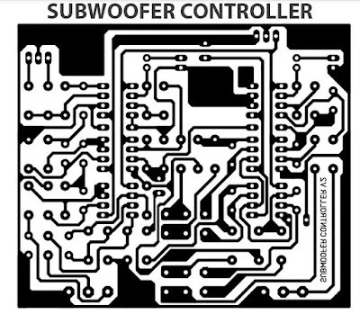
PCB Layout Subwoofer Controller NE5532
In this post, Elcircuit will share the PCB Layout of the Subwoofer Controller, this subwoofer controller circuit is very suitable for amplifiers made to control subwoofer speakers. You can download the PCB Layout of the Subwoofer controller in the form of a PDF file, for those who like to print their own PCB, the following layout is perfect for you. The PCB Layout download link is at the end of the post
This subwoofer controller circuit uses 6 NE5532 Dual Op-Amp ICs, can also be replaced with JRC4558, TL072, or others. Supply uses a DC voltage ranging from 12-15VDC CT. Its input can be stereo with mono subwoofer output. PCB Layout is designed in a single layer, making it easier for you to create your own PCB. For the adjustments, there are LEVEL, Frequency, and PHASE.
And for the frequency adjust potentiometer, you can use a Quad potentiometer, for example, you can buy it here: https://www.aliexpress.com/item/32962342969.html
 |
| BOTTOM COPPER |
PCB Dimension 7.4cm x 8.7cm
The following is an example of a finished Subwoofer Controller using this PCB Layout.
 |
| Finished Subwoofer Controller |
Download

Hi what is High pass frequency in this design
ReplyDeleteIf any one use this Circuit, What is the result?
ReplyDeleteGOOD GOB
ReplyDelete