Simple Charging Circuit Monitor with 555 and LM3914
This is a simple charging circuit monitor that indicates whether the battery is being charged or not. This circuit consists of two general IC, transistor NPN, ten led 5mm, and a few discrete components. It can be divided into two parts voltmeter and a display controller. be.low the schematic of simple charging monitor by using IC 555 an LM3914.
At the circuit above, the voltmeter is produced by IC LM3914, the voltmeter is about 7V-16V started on LED1 that indicate 7V. And display controller is produced on IC 555 that connected in an astable module with output narrow-pulses. Output IC555 is driven by resistor R5 and R6. If you want blink fastly, use the resistor value R5 and R6 smaller than R7. For voltage calibration using Rv2 and Rv1.
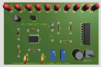
If you want to make it simple charging monitor you can follow this PCB layout design.


Post a Comment for "Simple Charging Circuit Monitor with 555 and LM3914"
Dont use outgoing links!