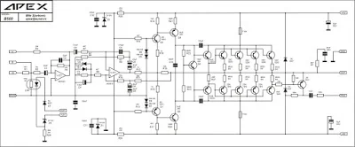
Power amplifier circuit schematic APEX following B500 visible part of the Pre-Amp use type IC NE5532. The output of IC NE5532 is given to the driver amplifier transistor. Part of these drivers will have two different outputs of phase from each other by 180 °. Part driver consists of transistors Q1, Q2, Q3 and Q4. Because the final amplifier circuit requires considerable input signal, then the driver is compiled with Darlington configuration.
 |
| Schematic Diagram |
 |
| Kits B500 APEX 500W Power Amplifier |
To be able to work optimally, the power amplifier circuit B500 APEX requires ration symmetrical voltage of ± 90 volts, with a current 15-20 Ampere. Use the original transistor amplifier, especially on the final / final, because the source of the applied voltage (± 90 volts) just for the ideal transistor or original. If unsure transistor used is not genuine, then do not ever use a working voltage of ± 90 Volts, because it can lead to the final amplifier transistor broken / damaged. To test this, use a voltage gradually, ranging from ± 25V, ± 30V, ± 45V, and so on.
In the assembly do not forget to give the room a good cooling in all transistor power, attach the fan (blower) to be stable when working at maximum volume primarily for purposes such as concerts stage.


do you have pdf file for this?
ReplyDelete