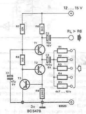
Very Simple Audio Mixer Circuit
A very simple audio mixer can be designed using this circuit diagram electronic project. Audio mixing is normally performed by a mixer with virtual ground, in which the various input signals are applied through series resistors to virtual ground, that at the inverting input of operational amplifier.
The audio mixer is a little different and uses the principle of common ground, the input voltages are converted into alternating current which, when summed, is the AC component of the collector. In the case of a common base configuration, emitter impedance is small and works as a virtual ground that is making it impossible to crosstalk between different input signals. The output signal is taken from the collector of Q1. Amplification circuit is equal to R6 + Ri, where Ri is the input resistance (= one of the resistances RI ... R5). The T1's emitter circuit has been provided a power source consisting of T2 and T3.
Q1's base voltage is set by resistors R7 and R8. Ensure that the capacitor C1 of T1 to be effectively disconnected.
Number of entries can be modified, increased or decreased as desired.

Post a Comment for "Very Simple Audio Mixer Circuit"
Dont use outgoing links!